
Ximu Electric
西东无问 南北有亩

Zhejiang Ximu Electric Co., Ltd. specializes in the R&D, production, sales and integrated services of smart power, intelligent evacuation, PV-storage-direct-flex system, DC power distribution and new power system equipment.
The company focuses on the fields of buildings, industrial parks, scenic spots, transportation, industry and new energy, providing safe, efficient, low-carbon and intelligent one-stop overall electrical solutions.
Supported by technological innovation from Southeast University and Nanjing University of Aeronautics and Astronautics, the core team has years of in-depth experience in power electronics and power systems, with mature capabilities in transforming scientific research achievements into industrialized applications.
Based on advanced manufacturing and power electronics technologies, Ximu Electric deeply integrates smart power and PV-storage-direct-flex technologies to facilitate the implementation of the dual-carbon strategy, and strives to become a leading domestic service provider of intelligent electrical solutions.
2.1 Project Background
Aiming at power supply pain points of two transformer districts and combining operating parameters of each 400kVA transformer, this project deploys energy storage systems to solve overvoltage caused by low district load or excessive photovoltaic power generation, as well as undervoltage during peak load periods. Meanwhile, it meets the daily operation requirement of two charge-discharge cycles per day, guarantees power supply stability, improves power quality, reduces grid operation and maintenance pressure, adapts to district operation demands after distributed photovoltaic integration, and realizes coordinated operation of source, grid, load and storage.
2.2 Core Requirements
Peak Shaving Requirement: Suppress grid peak power by absorbing redundant electric energy when district voltage exceeds upper limit, avoid voltage out-of-limit (exceeding safety threshold) and risk of equipment damage.
Valley Filling Requirement: Solve undervoltage at night; release electric energy to the grid during off-peak hours to boost line voltage, ensure normal operation of high-power appliances such as air conditioners and refrigerators, and improve power consumption experience for users.
Operation Mode: Realize two charging and two discharging cycles every day, fully utilize the benefit of peak-valley electricity price difference, balance voltage regulation effect and economy, and adapt to high-rate charge-discharge demands of batteries.
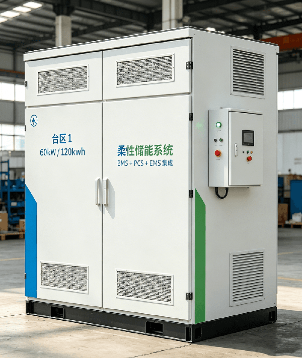
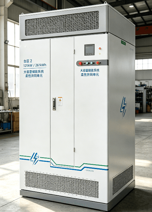
Energy Storage Configuration: Transformer District 1 (District 1 for short): 60kW/120kWh; Transformer District 2 (District 2 for short): 125kW/261kWh. Both are deployed on the low-voltage side of corresponding 400kVA transformers to realize on-site regulation.
2.3 Applicable Standards
This scheme strictly complies with Technical Conditions for Control Devices of Distributed Energy Storage Systems Connected to Distribution Transformer Districts (T/CES 299-2024), Technical Guidelines for Grid-Connection of Distributed Electrochemical Energy Storage on Transformer District Side (T/CI 1120-2025), Guidelines for Power System Security and Stability and relevant grid-connected specifications for distribution energy storage issued by local power grid companies, ensuring safe grid connection and compliant operation. It also meets national mandatory inspection standards for lithium iron phosphate batteries (GB/T 36276).
3.1 Design Principles
Safety First: Adopt energy storage equipment with high safety level, equipped with complete fire protection, lightning protection and overload protection, build a multi-level electrical protection system of "Cell – Module – String – System" to eliminate potential safety hazards.
Precise Demand Matching: Energy storage power and capacity match district load characteristics and 400kVA transformer capacity to guarantee peak shaving and valley filling effects, strictly satisfy two charge-discharge cycle requirements per day, and take battery cycle life into consideration.
Intelligent Control: Rely on EMS Energy Management System to realize automatic charge-discharge, voltage regulation, fault early warning and remote monitoring, reduce manual intervention and improve operation efficiency.
Reasonable Economy: Optimize equipment selection and operation strategy, prioritize highly integrated and long-life products to lower initial investment and later operation & maintenance costs, and increase revenue via arbitrage of peak-valley electricity prices.
Strong Expandability: Modular system design supports multi-unit parallel connection and cluster management, reserves expansion interfaces for future demands of load growth and grid upgrading.
3.2 System Architecture
The energy storage system of each transformer district adopts an integrated architecture of "Energy Storage Battery Pack + BMS Battery Management System + PCS Power Conversion System + EMS Energy Management System + Auxiliary Protection System", deployed on the 0.4kV low-voltage side of transformers and independently connected to district power grid. It forms a closed-loop regulation system together with transformers and loads, realizing internal energy self-regulation without scheduling from the main grid, equivalent to a "giant intelligent power bank plus voltage stabilizer" for the transformer district.
Core System Logic: EMS collects real-time parameters including district voltage, current, load power and grid frequency, issues instructions to control PCS switching between charging and discharging according to preset strategies. BMS monitors battery status in real time to ensure safe and stable battery operation. The auxiliary protection system deals with abnormalities such as overcurrent, overvoltage and short circuit to guarantee system safety throughout its whole lifecycle.
3.3 Overall Topology
Grid (10kV) → 400kVA Transformer → Low-Voltage Distribution Cabinet → Energy Storage System (PCS + Battery Pack + BMS + EMS) → District Load; The EMS communicates with PCS, BMS, low-voltage distribution cabinet and transformer measurement & control devices respectively, acquires real-time operating data and issues control instructions to realize closed-loop control of "Collection – Analysis – Decision – Execution". Meanwhile, it supports docking with grid dispatching platform and cloud operation & maintenance platform to implement remote monitoring and strategy issuing.
According to energy storage capacity requirements of the two districts, highly integrated outdoor integrated energy storage cabinets are selected, integrating battery system, PCS, BMS, EMS, temperature control, fire protection and other functions. They adapt to outdoor installation, reduce floor space and simplify deployment procedures. Detailed configurations are as follows:
4.1 Configuration of District 1 (60kW/120kWh)
| Equipment Name | Specification & Parameter | Quantity | Function Description |
| Energy Storage Battery Pack | Lithium iron phosphate cell, single cell voltage 3.2V, cycle life ≥ 8000 times, capacity attenuation ≤ 20%, monthly self-discharge rate ≤ 3%, total capacity 120kWh, operating voltage range 2.8~3.65V | 1 Set | Core energy storage unit for electric energy storage and release, adapting to high-frequency two charge-discharge cycles per day; equipped with flame retardant and thermal runaway isolation protection |
| BMS Battery Management System | Two-level architecture (BCU cabinet level + BMU module level), SOC error ≤ 1%, monitors cell voltage and temperature, realizes balance management, overcharge/over-discharge/over-temperature protection, supports communication with EMS and PCS | 1 Set | Guarantees safe battery operation, optimizes charge-discharge strategy, extends battery service life and uploads real-time battery status data |
| PCS Power Conversion System | Rated power 60kW, bidirectional conversion, efficiency ≥ 98%, response time ≤ 80ms, input voltage matches battery pack range, output voltage 380V (three-phase four-wire or three-phase three-wire), supports grid-connected/off-grid switching | 1 Unit | Realizes bidirectional conversion between DC and AC power, executes charge-discharge instructions from EMS, regulates output power and meets grid voltage & frequency requirements |
| EMS Energy Management System | Industrial multi-core processor, multiple Ethernet, RS485 and CAN interfaces, compatible with Modbus-TCP and MQTT protocols, with functions of data acquisition, strategy control, fault early warning and remote monitoring | 1 Set | Core system control unit, formulates charge-discharge strategies, coordinates operation of all equipment, solves peak shaving and valley filling problems and implements two charge-discharge cycle mode |
| Auxiliary Protection System | Including surge arrester, circuit breaker, fuse and insulation monitoring device, integrated three-dimensional protection system of "Detection + Suppression + Explosion Venting + Fire Protection" | 1 Set | Prevents lightning strike, overcurrent, short circuit and insulation faults, responds to fire emergencies and ensures safety of system and power grid |
| Temperature Control System | Intelligent air cooling, temperature control range -20℃~55℃, cell temperature difference ≤ 5℃, adapts to outdoor operation environment | 1 Set | Maintains batteries within optimal operating temperature range, avoids performance degradation and shortened service life caused by excessive high/low temperature |
| Energy Storage Cabinet | Outdoor integrated cabinet, IP54 protection grade, floor area ≤ 1.2 ㎡, dual-compartment separated design (battery compartment + electrical compartment) for easy maintenance | 1 Unit | Integrates all equipment, dustproof, waterproof and anti-corrosion, suitable for outdoor installation and simplifies deployment & maintenance |
4.2 Configuration of District 2 (125kW/261kWh)
| Equipment Name | Specification & Parameter | Quantity | Function Description |
| Energy Storage Battery Pack | Lithium iron phosphate cell, single cell 3.2V, cycle life ≥ 8000 times, capacity attenuation ≤ 20%, monthly self-discharge rate ≤ 3%, total capacity 261kWh; battery string composed of 5 parallel 166.4V/314Ah modules (1P260S, 832V/314Ah) | 1 Set | Core energy storage unit matching 125kW power output, excellent high-frequency charge-discharge performance, meeting requirements of two charge-discharge cycles, peak shaving and valley filling |
| BMS Battery Management System | Two-level architecture (BCU cabinet level + BMU module level), SOC error ≤ 1%, supports daisy-chain communication, collects real-time cell voltage, temperature, total voltage and charge-discharge current, with balance, protection and state estimation functions | 1 Set | Accurately controls battery status, prevents overcharge and over-discharge, optimizes charge-discharge curve, extends battery life and interacts with EMS & PCS in real time |
| PCS Power Conversion System | Rated power 125kW, bidirectional conversion, efficiency ≥ 98%, response time ≤ 80ms, input voltage matches 832V battery string, output voltage 380V (three-phase four-wire), supports grid-connected/off-grid operation and multi-unit parallel connection | 1 Unit | Realizes bidirectional power conversion, precisely executes EMS instructions, adjusts charge-discharge power, has functions of grid voltage regulation and harmonic treatment to support stable grid operation |
| EMS Energy Management System | Industrial multi-core processor, multiple interfaces, compatible with mainstream communication protocols, with intelligent scheduling, load forecasting, fault diagnosis and remote operation & maintenance functions, accessible to cloud platform | 1 Set | Overall system operation coordination, formulation of two charge-discharge strategies, solving peak shaving and valley filling, linkage control of subsystems to realize intelligent management |
| Auxiliary Protection System | Surge arrester, circuit breaker, fuse, insulation monitoring device, integrated perfluorohexanone fire protection and explosion venting device, multi-level short-circuit and overcurrent protection | 1 Set | Comprehensive system safety guarantee, coping with abnormalities such as lightning strike, short circuit and fire to ensure stable operation of equipment and power grid |
| Temperature Control System | Intelligent liquid cooling unit with circulating pipeline + liquid cooling plate design, temperature control range -25℃~55℃, cell temperature difference ≤ 3℃, service life increased by over 20% compared with air cooling | 1 Set | Precisely regulates battery temperature to dissipate heat generated by high-frequency charge-discharge, stabilizes battery performance and prolongs service life |
| Energy Storage Cabinet | Outdoor integrated liquid cooling cabinet, IP55 protection grade, floor area about 1.4 ㎡, dual-compartment separated modular layout, supports hot maintenance with liquid retained | 1 Unit | Integrates all equipment with compact structure, convenient installation, adapts to harsh outdoor environment and reduces operation & maintenance difficulty |
4.3 Equipment Selection Explanation
1. Battery Selection: Lithium iron phosphate battery is preferred, featuring high safety performance and long cycle life (≥8000 cycles, SOH≥70%), suitable for daily two high-frequency charge-discharge cycles with slow capacity attenuation, meeting long-term operation requirements of district energy storage. It also passes national mandatory inspection standards to ensure operation safety.
2. PCS Selection: Bidirectional high-efficiency converter with response time ≤ 80ms to meet rapid voltage regulation demands, efficiency ≥ 98% to reduce energy loss, supports grid-connected/off-grid switching and can act as backup power supply for critical loads during grid abnormalities, with grid support capability to improve power quality.
3. EMS Selection: Industrial-grade EMS system with high compatibility and reliability, supporting multi-device communication and data acquisition, flexible strategy configuration to adjust charge-discharge strategy dynamically according to district load and voltage fluctuation, as well as remote monitoring and maintenance to cut labor cost.
4. Temperature Control System: Air cooling is adopted for District 1 according to capacity demand, while high-efficiency liquid cooling system is applied for District 2 to control cell temperature difference within 5℃, avoid overheating caused by frequent charge-discharge, extend battery life and adapt to various outdoor ambient temperatures.
5.1 Installation Location Selection
The energy storage cabinets of both districts are installed in open outdoor areas beside corresponding 400kVA transformers, complying with the following requirements: Distance to transformer low-voltage distribution cabinet ≤ 10m to reduce line loss, facilitate cable connection and minimize voltage drop impact.
The site shall be flat and solid with bearing capacity ≥ 2.5t/㎡ (matching cabinet weight), no water accumulation, unobstructed, well ventilated and away from direct sunlight.
Keep away from flammable & explosive materials and residential areas (distance ≥ 5m) in accordance with fire codes; reserve maintenance space ≥ 1.5m around cabinets for equipment overhaul.
5.2 Electrical Connection
1. Connection between energy storage system and transformer low-voltage side: Connect PCS output terminal of energy storage cabinet to low-voltage distribution cabinet via copper cables, cable specification selected by power rating (District 1: 35mm²; District 2: 70mm²). Adopt conduit laying with complete insulation protection to prevent short circuit and electric leakage.
2. Control wiring: EMS connects with PCS, BMS, low-voltage distribution cabinet and transformer measurement & control devices via RS485/Ethernet ports for data interaction and instruction issuing; it can also access grid dispatching system to upload operating data and receive dispatching instructions if required.
3. Earthing System: Reliably earth energy storage cabinet, PCS, battery pack and low-voltage distribution cabinet to form a unified earthing network with earthing resistance ≤ 4Ω, preventing live equipment enclosure and protecting personal & equipment safety.
5.3 Installation Procedure
1. Site Preparation: Clean installation site, level ground, pour concrete foundation (thickness ≥ 20cm), construct earthing network and ensure qualified earthing resistance.
2. Equipment Delivery: Transport integrated energy storage cabinets and auxiliary equipment to installation positions, hoist in place, level and fix firmly.
3. Electrical Installation: Lay power cables connecting energy storage system and low-voltage distribution cabinet, arrange control wiring, conduct insulation test and wiring inspection to guarantee correct and firm connection.
4. System Commissioning: Complete individual commissioning of each equipment (BMS, PCS, EMS respectively), then carry out joint system commissioning, simulate scenarios such as charge-discharge and voltage regulation, and optimize control parameters.
5. Acceptance & Commissioning: Organize relevant parties for acceptance after qualified commissioning, connect to power grid for official operation upon approval, and activate remote monitoring function simultaneously.
5.4 Construction Requirements
The construction contractor shall hold relevant qualifications; construction personnel must work with valid certificates, operate strictly in accordance with electrical construction specifications and take safety protection measures.
Cables shall be laid neatly with clear marking and complete conduit protection to avoid extrusion and damage; insulate joints thoroughly to prevent electric leakage.
Follow equipment manual strictly during commissioning, focus on testing charge-discharge function, voltage regulation precision and protection performance to ensure stable system operation.
Clean up site after construction, sort and archive construction documents including wiring diagrams, commissioning reports and acceptance reports.
As the core of district energy storage system, EMS Energy Management System is responsible for overall equipment operation coordination and charge-discharge strategy formulation to realize voltage regulation, strictly satisfying three core demands of peak shaving, valley filling and two charge-discharge cycles daily. It adopts closed-loop mode of "Real-time Monitoring – Intelligent Analysis – Instruction Issuing – Feedback Adjustment", dynamically optimizes control strategy combined with district load characteristics, voltage fluctuation and battery status, and supports both cloud remote regulation and local autonomous operation. Detailed logic is as follows:
6.1 Core Control Objectives
• Peak Shaving: Trigger energy storage charging to absorb redundant power when district voltage exceeds upper limit or reverse power delivery occurs, restrain voltage rise, smooth grid peak load and avoid voltage out-of-limit.
• Valley Filling: Activate energy storage discharging to supplement grid power and lift line voltage when district voltage drops below lower limit or severe undervoltage occurs during evening peak hours, guarantee normal load operation and fill load valley.
• Two Charge-Discharge Cycles: Complete two charging and two discharging processes at fixed daily periods; adjust charge-discharge power and duration dynamically according to battery capacity and load demand, maintain battery SOC within reasonable range (5%~95%) to avoid overcharge/over-discharge and extend battery life.
6.2 Data Collection & Monitoring
EMS collects the following key data in real time as basis for control decision-making, and uploads data to cloud platform for real-time monitoring and storage:
• Grid Parameters: Three-phase low-voltage side voltage, current, frequency, power factor and reverse power of transformer district; real-time monitoring of voltage fluctuation and reverse power delivery.
• Energy Storage System Parameters: Battery SOC (State of Charge), cell voltage, cell temperature, total battery voltage, charge-discharge current and power; PCS operating status and conversion efficiency; BMS protection status.
• Load Parameters: Total district load power and variation trend, identify peak & off-peak periods to match charge-discharge strategy.
• Equipment Status: Operating status of energy storage cabinet temperature control system, fire protection system and auxiliary protection system for timely abnormality detection.
6.3 Adjustment for Special Conditions
1. If abnormal voltage (over-high/over-low) exceeds normal range in a certain period, execute peak shaving/valley filling instruction with priority, suspend scheduled two charge-discharge periods, adjust time schedule after voltage recovers to ensure completion of two cycles within the same day.
2. In case of battery abnormalities (over-temperature, abnormal cell voltage, etc.), BMS sends alarm signal, EMS immediately stops charge-discharge and activates protection mechanism, uploads fault information and resumes normal operation after troubleshooting.
3. Upon grid faults (power outage, frequency abnormality), PCS automatically switches to stop/standby mode, returns to grid-connected mode after grid recovery, adjusts charge-discharge strategy to complete remaining two charge-discharge cycles.
6.4 Remote Monitoring & Operation & Maintenance Logic
• Real-time Monitoring: EMS communicates with cloud platform and grid dispatching center via 4G/Ethernet, uploads real-time system operating data (voltage, current, SOC, equipment status, etc.), supporting remote viewing via PC and mobile terminals.
• Fault Early Warning & Handling: Trigger local audible & visual alarm plus cloud alarm once equipment abnormalities (battery over-temperature, PCS fault, abnormal voltage, etc.) occur; record fault information automatically, take emergency measures (pause charge-discharge, cut off circuit, etc.) and notify maintenance personnel for timely disposal.
• Remote Regulation: Maintenance staff can remotely adjust charge-discharge time, power, voltage threshold and other parameters via cloud platform to adapt to changing district operating conditions without on-site operation.
• Data Statistics & Analysis: EMS automatically counts daily charge-discharge times, electricity quantity, voltage regulation effect and battery degradation data, generates daily, weekly and monthly reports to support maintenance decision-making and strategy optimization.
7.1 Commissioning Contents
• Individual Equipment Commissioning: Test BMS, PCS, EMS, temperature control system and fire protection system separately, check operating status, parameter setting and protection functions to ensure normal equipment operation.
• Joint Commissioning Test: Operate all equipment coordinately, simulate scenarios of two charge-discharge cycles, peak shaving and valley filling, verify accuracy and response speed of EMS control logic, inspect voltage regulation effect and optimize control parameters.
• Grid-Connection Test: Connect energy storage system to power grid, test grid-connection stability and power quality (voltage, frequency, harmonic), comply with grid connection specifications without reverse power delivery or voltage out-of-limit issues.
• Protection Function Test: Simulate abnormalities such as overcharge, over-discharge, over-temperature, short circuit and lightning strike, verify response speed and effectiveness of protection system to guarantee safety of equipment and power grid.
7.2 Trial Operation Scheme
Enter trial operation phase for 7 days after qualified commissioning with specific requirements as follows:
• During trial operation, the system runs according to preset two charge-discharge strategy and peak-valley regulation logic; EMS monitors operating data in real time and records voltage variation, charge-discharge status and equipment conditions.
• Check equipment operation daily, eliminate hidden faults and record trial operation data including charge-discharge times, electricity quantity, voltage regulation range and battery SOC variation.
• Stop operation for timely troubleshooting and parameter optimization if abnormal voltage or equipment faults occur during trial operation to guarantee stable system performance.
• Sort out trial operation data after completion, analyze overall system performance, further optimize and adjust if requirements are not met before formal commercial operation.
8.1 Fault Handling
Establish emergency fault handling mechanism and clear workflow to ensure timely troubleshooting and minimize downtime:
• Fault Reporting: Once maintenance personnel receive local or cloud alarms, record fault type, occurrence time and phenomenon immediately and report to relevant person in charge.
• Fault Troubleshooting: Analyze root causes (battery abnormality, PCS failure, line fault, etc.) according to fault information and formulate disposal plan.
• Fault Disposal: Arrange professional technicians for troubleshooting with complete safety protection measures to avoid secondary faults; test equipment operation after repair to confirm fault elimination.
• Fault Filing: Archive whole process, root cause and result of disposal, analyze fault pattern, optimize maintenance scheme and prevent recurrence of similar failures.
8.2 Battery Maintenance
As the core component of energy storage system, batteries shall be maintained intensively to extend service life:
• Prevent battery overcharge and over-discharge, strictly control SOC within 5%~95%, inspect battery balance status regularly to guarantee consistency of battery pack.
• Maintain proper ambient temperature for batteries, check performance of temperature control system periodically to avoid accelerated degradation caused by excessively high or low temperature.
• Avoid long-term idle storage; if the system is out of service for a long time, perform one complete charge-discharge cycle every three months (charge to 70% SOC, discharge to 30% SOC) to retain battery activity.
9.1 Equipment Safety
• Adopt equipment complying with national safety standards with complete protection functions (overcharge, over-discharge, over-temperature, short circuit, lightning protection, etc.) and integrated three-dimensional fire protection system.
• Energy storage cabinet with IP55 protection grade for dustproof, waterproof and anti-corrosion performance against outdoor environmental damage.
• Conduct regular equipment inspection and maintenance, replace aging components timely and eliminate hidden dangers to ensure safe operation.
9.2 Electrical Safety
• Execute electrical connection strictly in accordance with specifications with full insulation protection to prevent short circuit and electric leakage; lay cables in standardized way with clear identification.
• Reliable system earthing with earthing resistance ≤ 4Ω; reliably earth equipment enclosure and cable shielding layer to prevent electric shock hazard.
• Equip lightning protection devices against lightning damage; suspend system operation and take protective measures during thunderstorms.
 WeChat Customer Service
 Weixin Channels
 WeChat Official Account


